 https://stackoverflow.com/questions/15408644
 italiano
 english
 français
 española
 中国
中国 日本の
日本の العربية
 Deutsch
 한국어
한국어 Português
 Russian
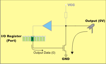
It's the correct way, there must be something wrong with your simulation. The 8051 pins have this kind of circuit:

(source)
Note the pullup to Vcc is optional, check the datasheet of your particular chip.
This circuit works such that if you set a pin to 0, the output will be pulled to ground and can only be read as 0 because externally you can't pull it high. If you want to allow both levels to be input, you have to set the pin to 1. In this case you can:
- leave output floating if you have internal pullups (reads as
1) - pull output to
Vcc(reads as1) - pull output to ground (reads as
0)
It follows that if you connect a button you should wire it such that it pulls the pin to ground. Add an external pullup resistor if required.
Update
to make this point clear: if you wire the button as directed above (ie. pushed button grounds the pin) the input will be read as 1 if button is not pressed, and as 0 if button is pressed. This is the usual way to connect buttons.
Illustration using MCU 8051 IDE. Notice two switches are connected to port 1 pins 7 and 6 (ie. the two top bits), one is open the other is closed (pushed).
If the port bits are set to zero, input will be zero no matter the state of the switches:

If the port bits are set to one, input will be 1 for an open and 0 for a closed switch:

The red wiring leading to the leftmost switch indicates that P1.7 is at Vcc (because output is 1 and it is not pulled down by the switch).
