I am using one of the PRU units on the AM335x to drive 4 of the GPIO pins on the BeagleBone(GPIO1_2, GPIO1_3, GPIO1_6, GPIO1_7) and I want to synchronize the edge transitions(my full source code is at the bottom).
With the Beaglebone to set the output HI on a pin, you set the corresponding bit to 1 at address 0x4804c194 then to set it LO, you set the bit to 1 at address 0x4804c190. So my PRU assembly code first sets the output HI bits then sets the output LO bits:
 MOV r4, GPIO1 | GPIO_CLEARDATAOUT
 MOV r5, GPIO1 | GPIO_SETDATAOUT
 ...
 ...
//Loop the following:
MAIN_LOOP:
    LBCO r2, CONST_PRUDRAM, r1, 8//Read in LO and HI data into r2/r3
    SBBO r3, r5, 0, 1  //Write HI data
    SBBO r2, r4, 0, 1  //Write LO data
    ADD r1, r1, 8
    QBEQ EXIT, r1, 112  //Done?  Exit
    QBA MAIN_LOOP
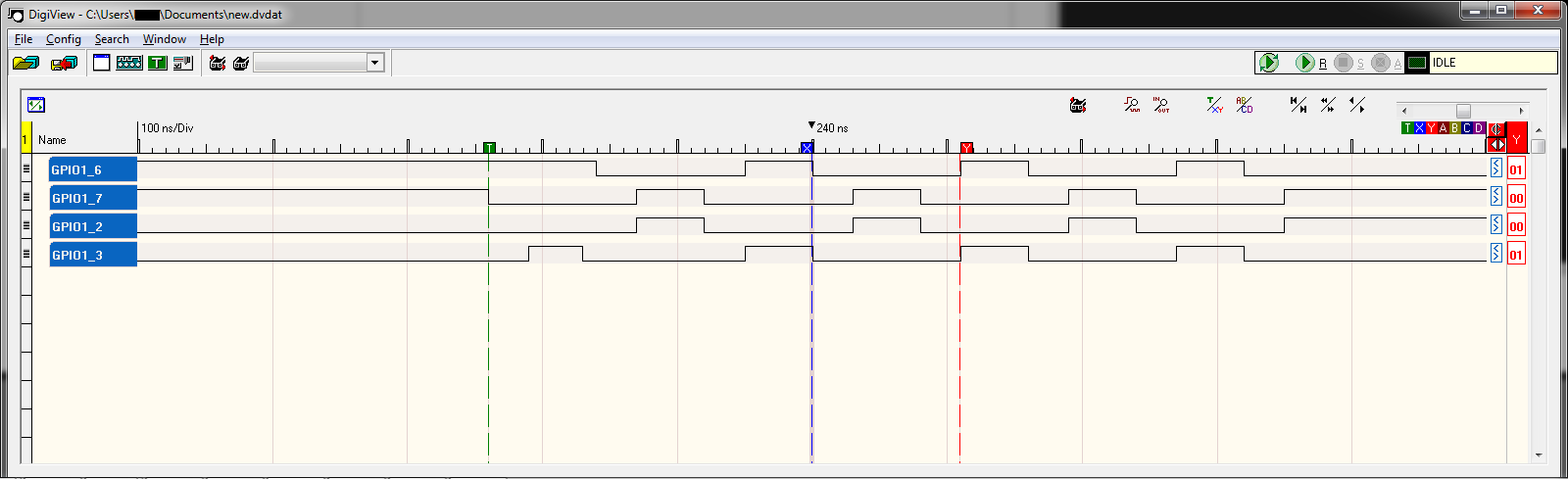
due to how many cycles it takes to run each one, the LO period is significantly longer than the HI(50ns vs 110ns). Unfortunately I'm too new to post images, here is a link to a logic analyzer screenshot from the previous code
To even the timing out, I alternate between setting the HI and LO bits so the periods are equal at 80ns, but the HI and LO transitions are 80ns offset from each other:
 MOV r4, GPIO1 | GPIO_CLEARDATAOUT
 MOV r5, GPIO1 | GPIO_SETDATAOUT
 ...
 ...
//Loop the following:
MAIN_LOOP:
    LBCO r2, CONST_PRUDRAM, r1, 8 //Read in LO and HI data into r2/r3
    SBBO r3, r5, 0, 1  //Write HI data
    SBBO r2, r4, 0, 1  //Write LO data
    ADD r1, r1, 8
    QBEQ EXIT, r1, 112
    QBA MAIN_LOOP2

MAIN_LOOP2:
    LBCO r2, CONST_PRUDRAM, r1, 8 //Read in LO and HI data into r2/r3
    SBBO r2, r4, 0, 1  //Write LO data
    SBBO r3, r5, 0, 1  //Write HI data
    ADD r1, r1, 8
    QBEQ EXIT, r1, 112
    QBA MAIN_LOOP
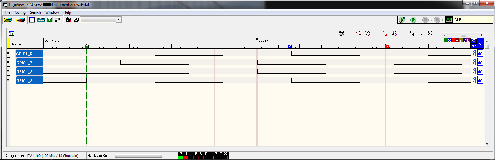
Here too is a logic analyzer screenshot of the previous code.
So my question is how can I get the edge transitions to occur at the same time? I.e. if you compare GPIO1_6 and GPIO_7, at the center of the screenshot is 200ns when GPIO1_7 transitioned LO then 50ns BEFORE, GPIO1_6 transitioned HI, I'd like them both to transition at the same time. I don't mind slowing it down to accomplish this.
Here is my source code:
File: main.p
.origin 0
.entrypoint START

#include "main.hp"

#define GPIO1 0x4804c000
#define PINMUX 0x44E10800

#define GPIO_CLEARDATAOUT 0x190
#define GPIO_SETDATAOUT 0x194
#define GPIO_DIRECTION 0x134
#define GPIO_DIRECTION2 0x142


START:
    //clear STANDBY_INIT bit
    LBCO r0, C4, 4, 4
    CLR r0, r0, 4
    SBCO r0, C4, 4, 4

    //TODO SET the pin(s) direction to OUTPUT, currently sets ALL bits to output
    MOV r4, GPIO1 | GPIO_DIRECTION
    MOV r7, 0x00000000
    SBBO r7, r4, 0, 4
    MOV r4, GPIO1 | GPIO_DIRECTION2
    SBBO r7, r4, 0, 4

    //TODO SET the pins to GPIO Mode aka MODE 7, i.e. GPIO1_6 to mode GPIO1_6

    MOV r4, GPIO1 | GPIO_CLEARDATAOUT
    MOV r5, GPIO1 | GPIO_SETDATAOUT

    //Read in number of patterns into R20
    LBCO r20, CONST_PRUDRAM, 0, 4

    //Set R1 to 4bytes
    MOV r1, 32

MAIN_LOOP:
    //Read pin data into r2/r3
    LBCO r2, CONST_PRUDRAM, r1, 8
    //Set Pin outputs by writing to the GPIO1 memory
    //SBBO r2, r4, 0, 8
    SBBO r3, r5, 0, 1
    SBBO r2, r4, 0, 1
    //Increment Pin Data to next 8 bytes
    ADD r1, r1, 8
    //Check if done, after 80bytes
    QBEQ EXIT, r1, 112
    QBA MAIN_LOOP2
    //QBA MAIN_LOOP //To get first screenshot, comment line before & uncomment this

MAIN_LOOP2:
    //Read pin data into r2/r3
    LBCO r2, CONST_PRUDRAM, r1, 8
    //Set Pin outputs by writing to the GPIO1 memory
    //SBBO r2, r4, 0, 8
    SBBO r2, r4, 0, 1
    SBBO r3, r5, 0, 1
    //Increment Pin Data to next 8 bytes
    ADD r1, r1, 8
    //Check if done, after 80bytes
    QBEQ EXIT, r1, 112
    QBA MAIN_LOOP

EXIT:

#ifdef AM33XX
    // Send notification to Host for program completion
    MOV R31.b0, PRU0_ARM_INTERRUPT+16
#else
    MOV R31.b0, PRU0_ARM_INTERRUPT
#endif
HALT
File main.c:
#include <stdio.h>
// Driver header file
#include <prussdrv.h>
#include <pruss_intc_mapping.h>

#define PRU_NUM         0
#define AM33XX

static int LOCAL_exampleInit ();

static void *pruDataMem;
static unsigned int *pruDataMem_int;

int main (void)
{
    unsigned int pindata[12];
    unsigned int pinmask = 0;
    int j = 0;

    unsigned int ret, i;
    tpruss_intc_initdata pruss_intc_initdata = PRUSS_INTC_INITDATA;

    /* Initialize the PRU */
    printf("\nINFO: Starting %s.\r\n", "main");
    prussdrv_init ();

    /* Open PRU Interrupt */
    ret = prussdrv_open(PRU_EVTOUT_0);
    if (ret)
    {
        printf("prussdrv_open open failed\n");
        return (ret);
    }

    /* Get the interrupt initialized */
    prussdrv_pruintc_init(&pruss_intc_initdata);

    /* Initialize memory */
    printf("\tINFO: Initializing.\r\n");
    LOCAL_Init();

    pruDataMem_int[0] = 10; //ignored

    //Load up the pin data
    pruDataMem_int[4] = 0x88;
    pruDataMem_int[5] = 0x44;

    pruDataMem_int[6] = 0x44;
    pruDataMem_int[7] = 0x88;
    pruDataMem_int[8] = 0x88;
    pruDataMem_int[9] = 0x44;

    pruDataMem_int[10] = 0x44;
    pruDataMem_int[11] = 0x88;
    pruDataMem_int[12] = 0x88;
    pruDataMem_int[13] = 0x44;

    pruDataMem_int[14] = 0x44;
    pruDataMem_int[15] = 0x88;
    pruDataMem_int[16] = 0x88;
    pruDataMem_int[17] = 0x44;

    pruDataMem_int[18] = 0x44;
    pruDataMem_int[19] = 0x88;
    pruDataMem_int[20] = 0x88;
    pruDataMem_int[21] = 0x44;
    pruDataMem_int[22] = 0x44;
    pruDataMem_int[23] = 0x88;

    printf("\tINFO: Executing PRU.\r\n");
    prussdrv_exec_program (PRU_NUM, "main.bin");

    // Wait until PRU0 has finished execution

    printf("\tINFO: Waiting for HALT command.\r\n");
    prussdrv_pru_wait_event (PRU_EVTOUT_0);
    printf("\tINFO: PRU completed transfer.\r\n");
    prussdrv_pru_clear_event (PRU0_ARM_INTERRUPT);

    // Disable PRU and close memory mapping
    prussdrv_pru_disable (PRU_NUM);
    prussdrv_exit ();

    return(0);
 }

static int LOCAL_Init ()
{
    prussdrv_map_prumem (PRUSS0_PRU0_DATARAM, &pruDataMem);
    pruDataMem_int = (unsigned int) pruDataMem;

    pruDataMem_int[0] = 0x00;
    pruDataMem_int[1] = 0x00;
    pruDataMem_int[2] = 0x00;
    pruDataMem_int[3] = 0x00;
    return(0);
}
File main.hp:
#ifndef _main_HP_
#define _main_HP_
#define AM33XX

#ifdef AM33XX

// Refer to this mapping in the file - \prussdrv\include\pruss_intc_mapping.h
#define PRU0_PRU1_INTERRUPT     17
#define PRU1_PRU0_INTERRUPT     18
#define PRU0_ARM_INTERRUPT      19
#define PRU1_ARM_INTERRUPT      20
#define ARM_PRU0_INTERRUPT      21
#define ARM_PRU1_INTERRUPT      22

#define CONST_PRUDRAM   C24
#define CONST_SHAREDRAM C28
#define CONST_L3RAM     C30
#define CONST_DDR       C31

// Address for the Constant table Programmable Pointer Register 0(CTPPR_0)
#define CTBIR_0         0x22020
// Address for the Constant table Programmable Pointer Register 0(CTPPR_0)
#define CTBIR_1         0x22024

// Address for the Constant table Programmable Pointer Register 0(CTPPR_0)
#define CTPPR_0         0x22028
// Address for the Constant table Programmable Pointer Register 1(CTPPR_1)
#define CTPPR_1         0x2202C

#else

// Refer to this mapping in the file - \prussdrv\include\pruss_intc_mapping.h
#define PRU0_PRU1_INTERRUPT     32
#define PRU1_PRU0_INTERRUPT     33
#define PRU0_ARM_INTERRUPT      34
#define PRU1_ARM_INTERRUPT      35
#define ARM_PRU0_INTERRUPT      36
#define ARM_PRU1_INTERRUPT      37

#define CONST_PRUDRAM   C3
#define CONST_HPI       C15
#define CONST_DSPL2     C28
#define CONST_L3RAM     C30
#define CONST_DDR       C31

// Address for the Constant table Programmable Pointer Register 0(CTPPR_0)
#define CTPPR_0         0x7028
// Address for the Constant table Programmable Pointer Register 1(CTPPR_1)
#define CTPPR_1         0x702C

#endif

.macro  LD32
.mparam dst,src
    LBBO    dst,src,#0x00,4
.endm

.macro  LD16
.mparam dst,src
    LBBO    dst,src,#0x00,2
.endm

.macro  LD8
.mparam dst,src
    LBBO    dst,src,#0x00,1
.endm

.macro ST32
.mparam src,dst
    SBBO    src,dst,#0x00,4
.endm

.macro ST16
.mparam src,dst
    SBBO    src,dst,#0x00,2
.endm

.macro ST8
.mparam src,dst
    SBBO    src,dst,#0x00,1
.endm

#define sp r0
#define lr r23
#define STACK_TOP       (0x2000 - 4)
#define STACK_BOTTOM    (0x2000 - 0x200)

.macro stack_init
    mov     sp, STACK_BOTTOM
.endm

.macro push
.mparam reg, cnt
    sbbo    reg, sp, 0, 4*cnt
    add     sp, sp, 4*cnt
.endm

.macro pop
.mparam reg, cnt
   sub     sp, sp, 4*cnt
    lbbo    reg, sp, 0, 4*cnt
.endm
#endif //_main_HP_
 https://stackoverflow.com/questions/17804759
 italiano
 english
 français
 española
 中国
中国 日本の
日本の العربية
 Deutsch
 한국어
한국어 Português
 Russian